CAD Drawing - The digital CAD drawing of "form" and "object" refers to the process of using computer-aided design…
| Category | Frontier Technology |
|---|---|
| Standard size | Custom size |
| Supply | Single unit or batch · OEM to your drawing |
| Lead time | Standard 4–8 weeks after deposit (confirmed per contract) |
| Warranty | 1 year, structure and control |
| Documents | Specification sheet · control diagram · spare-part list |
A standard catalogue model: the dimensions, control package and finish are fixed, which is what keeps the price and the lead time predictable. Size, colour and interface language can be adapted without a new design cycle.
Standard models from this range are also listed in our online store, priced in USD — see the price yourself ↗
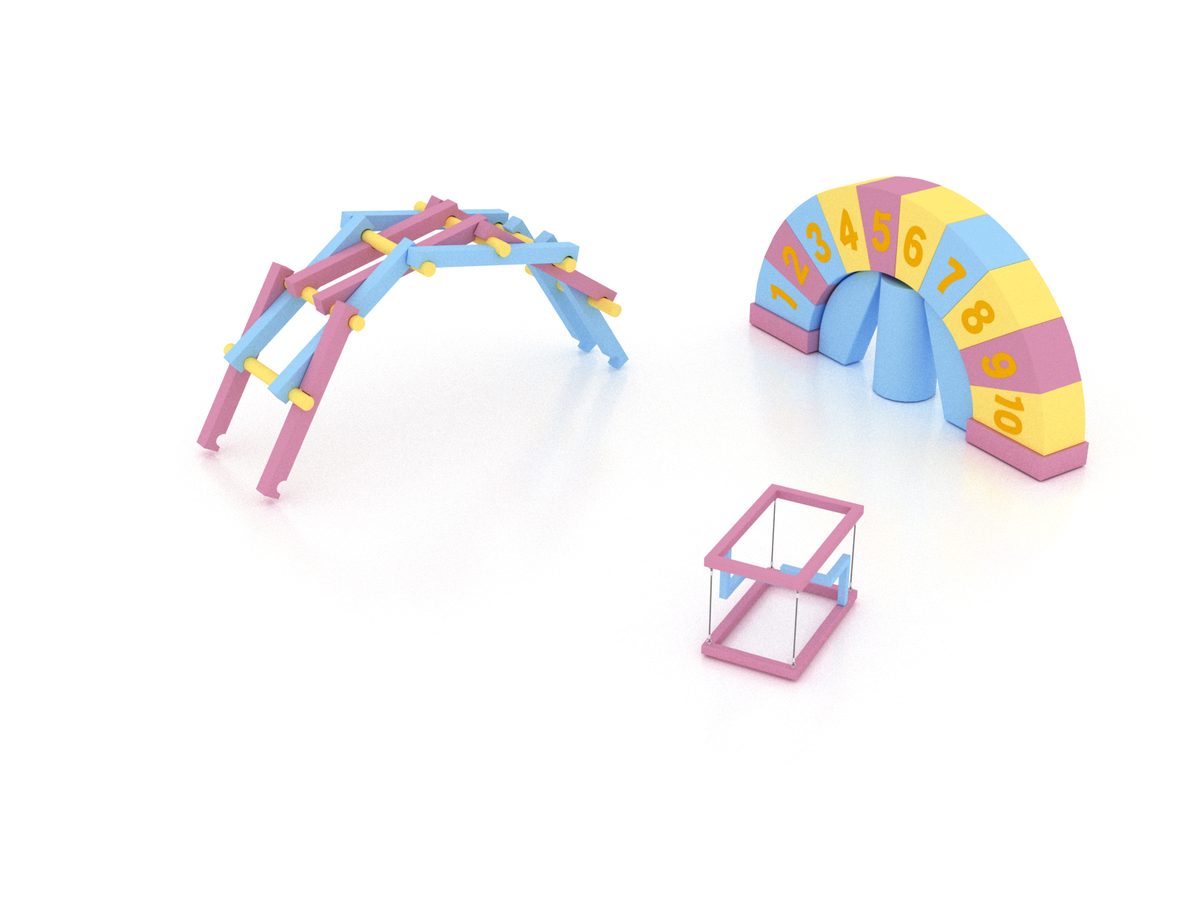
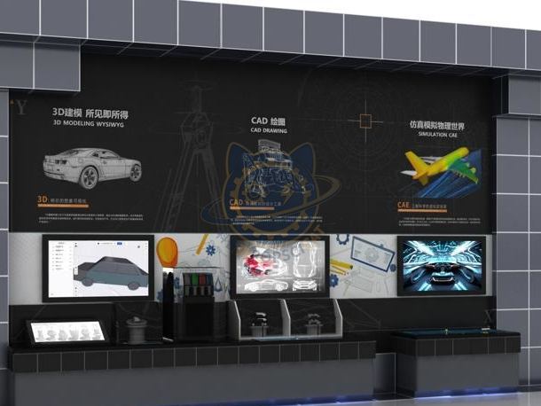
CAD Drawing - The digital CAD drawing of "form" and "object" refers to the process of using computer-aided design software to create accurate two-dimensional (2D) or three-dimensional (3D) technical drawings and models. CAD drawing is widely used in fields such as architecture, engineering, manufacturing, electronics, aerospace, automotive design, etc., for designing, planning, and analyzing various products or structures.
The unit is designed for unsupervised public use: controls are recessed or shielded, moving parts are enclosed, and the interface is operable by a child of about six with no instruction. Where a screen is used, the language can be switched without changing the hardware, and the content can be replaced on site.
CAD is the abbreviation for Computer Aided Design, which mainly uses computers and their graphic devices to assist designers in their design work. The correspondence between the three-dimensional shape of the design object and its representation on a two-dimensional plane, namely the relationship between solid and flat, is crucial for industrial design as it can accurately express and convey the designer's intentions, ensuring the accuracy and consistency of the manufacturing process. one Projection: When drawing a blueprint, designers need to project the three-dimensional shape of the model onto a two-dimensional plane to obtain the corresponding plan view. Projection can use different projection methods, such as orthogonal projection, perspective projection, etc., to accurately represent the appearance and structure of three-dimensional shapes in a plan view. two View: In a floor plan, designers typically draw multiple views, including front view, side view, top view, etc. Each view displays the projection of the 3D model in different directions, providing multiple angles for observation.
Every unit leaves the factory after a running test: mechanisms cycled, electronics burned in, edges dressed, fixings torqued and marked. Wear parts — bearings, sliders, lamps, belts, touch panels — are modular and listed on the spare-part sheet, so a venue technician can replace them without returning the exhibit. Crating is plywood with foam blocking; the loading plan and packing list travel with the shipment.
Other models from the Frontier Technology line, all held to the same specification and the same control package.

Build a span from interchangeable parts and load it until it fails.

Shape-memory alloy, aerogel and carbon fibre under the visitor's hand.

Build a lattice from magnetic balls and see why a crystal cleaves.

Four arms perform a synchronised routine behind a glass wall.
Attach a theme outline, a floor plan, or nothing at all — a photo of the space is enough to start. Quotations are issued against a real exhibit list, not per-square-metre guesses.
Scan to add us