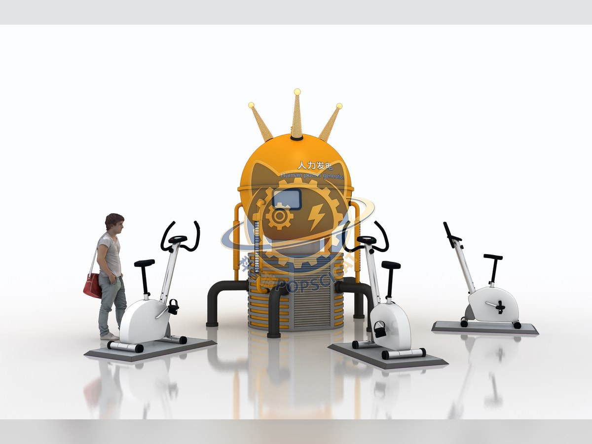
I. Purpose of the Exhibit This exhibit demonstrates the process of converting mechanical energy into electrical energy by manually rotating a conductive coil to cut through magnetic field lines, thereby generating an electric current. II. Scientific Principle When a DC generator is operating, an external mechanical force causes the conductor coil to rotate in a magnetic field and continuously cut through the magnetic field lines, generating an induced electromotive force. Figure 1 shows a schematic diagram of the operating principle of a typical DC generator. Figure 2 shows the operating process of the DC generator rotor winding at the moment it begins to rotate. When an external mechanical force drives the winding to rotate, coils ab and cd respectively perform the action of cutting magnetic lines of force. According to the principle of electromagnetic induction, an electric current is generated inside the winding. The direction of the current can be determined by the right-hand rule as follows: The induced current forms a circuit through coil dc → cb → ba, commutator 1, brush A, ammeter, brush B, and commutator 2. Figure 3 shows the operating process of the DC generator after the rotor winding has rotated 90°. When the winding rotates 90°, the two sides of the winding are in the neutral plane of the magnetic field, and the brushes do not come into contact with the commutator segments. No current flows through the winding, F=0, and the torque disappears. Figure 4 shows the operating process of the DC generator rotor winding after another 90° rotation. Under the action of external mechanical force, the rotor winding continues to rotate. At this time, the winding continues to cut the magnetic lines of force, and an induced current can be generated in the winding. This induced current forms a circuit through the winding ab→bc→cd, commutator 2, brush A, ammeter, brush B, and commutator 1. From this, it can be seen that the induced electromotive force in the rotor winding is an alternating electromotive force, while the electromotive force at the brushes AB is a direct current electromotive force. In other words, through the commutator working in conjunction with the brushes, the current output by the rotor winding is always in one direction, which is the working principle of a direct current generator. III. Functional Description (Technical Solution) The exhibit demonstrates the working principle of a generator, which is typically composed of components such as the stator, rotor, end caps, and bearings. The stator and rotor of the generator are connected and assembled by bearings and end caps, allowing the rotor to rotate within the stator, cutting through magnetic field lines. This action generates an induced electromotive force, which is led out through terminals and connected into a circuit, thereby producing an electric current. The exhibit combines interactivity, fun, and science. IV. Operating Instructions Sit on the bicycle, start pedaling to generate electricity, and illuminate the light strip in front. It is built for unsupervised public use: surfaces are robust and wipe-clean, there are no loose parts, and the interface works without instruction, so a child of about six can operate it on a busy floor.